Forced induction
Forced induction consist of mechanically increasing air density prior to fill the engine. A higher density means more molecules of air per volume, hence more fuel can be burned, leading to a higher power output for a smaller engine.
A small engine with forced induction will have a combustion that will produce as much power as a bigger NA engine, as long as it sucks the same amount of air (mass wise). But compressing the air − most of the time rather inefficiently − will require some work from the engine, thus reducing the overall power output (while burning the same amount of fuel). This will always give the advantage to the NA engine in both fuel consumption and power output. But forced induction can be a wiser choice when considering engine size and part load fuel consumption.
Furthermore, the temperature increase resulting from the air compression will increase the chances of pre-ignition in SI engines. Intercooling will reduce those odds and can even reduce compression work.
How to compress air
Piston air compressor
For education purposes, let's look at a simple single-acting air compressor cylinder as in the next figure.
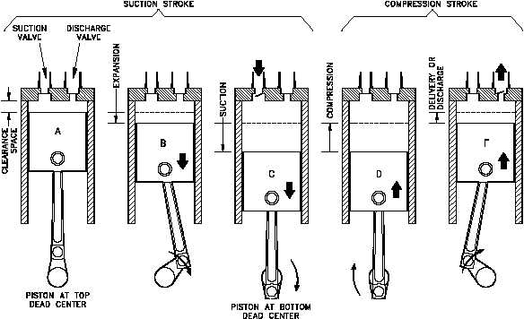
During the suction stroke the compressor piston starts its downward stroke and the air under pressure in the clearance space rapidly expands until the pressure falls below that on the opposite side of the inlet valve (Figures 2B and 2C). This difference in pressure causes the inlet valve to open into the cylinder until the piston reaches the bottom of its stroke (Figure 2C).
During the compression stroke the piston starts upward, compression begins, and at point D has reached the same pressure as the compressor intake. The spring-loaded inlet valve then closes. As the piston continues upward, air is compressed until the pressure in the cylinder becomes great enough to open the discharge valve against the pressure of the valve springs and the pressure of the discharge line (Figure 2E). From this point, to the end of the stroke (Figures 2E and 2A), the air compressed within the cylinder is discharged at practically constant pressure.
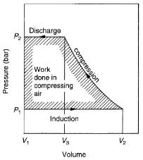
This type of compressor compresses the air BEFORE the discharge valve opens. Then, once the air is compressed, it displaces it toward the compressor's outlet. This is the most efficient way of compressing air. The PV diagram can be seen in the figure on the right.
Another advantage of such compressor is the fact that if the discharge valve does not open (because the pressure is too high at the compressor's outlet), the energy taken to compress the air is sent back to the crankshaft on the next downstroke when the air inside the cylinder decompresses; thus no energy loss (except for some friction). (See Pressure-Volume diagram for more info)
The reason this type of compressor is not used with an engine is its size. For example, increasing the volumetric flow rate of a typical 4-stroke engine by 35% would require the addition of a compressor which has a displacement of 68% of the engine displacement (135% ÷ 2; because the compressor has a 2-stroke cycle instead of 4). It is even worse if we consider the volumetric efficiency. This defy the purpose of compression since it would be better to use an engine with a displacement 35% larger.
Sliding vane supercharger
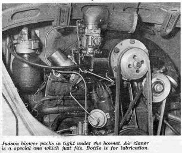
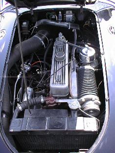
The sliding vane surpercharger was used on cars from the 20's until the 60's. It's main disadvantage is maintenance cost.
(detailed info)
|
| Sliding vane supercharger in a Volkswagen Beetle from the late 50's |
|
| Sliding vane supercharger in a 1956 MGA |
Operating principle
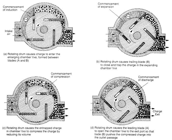
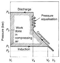
As one can see, there is an expansion phase ( from V2 to V3 ) at the beginning of the process which is undesirable as we will have to recompress the air afterward ( from V3 to V4 ). But the worst part, thermodynamically speaking, is that partially compressed air is presented to the outlet port which have a high boost pressure. This results in an equalisation process where the high pressure air from the outlet port goes back inside the supercharger. This process requires more work compared to a piston air compressor, as shown in the PV diagram. This will increase the temperature of the intake charge, especially when combined with friction of the blade against the casing of the compressor.